- 您现在的位置:买卖IC网 > Sheet目录471 > MAX19996ETP+T (Maxim Integrated)IC MIXER DOWNCONV 20-TQFN-EP
SiGe High-Linearity, 2000MHz to 3000MHz
Downconversion Mixer with LO Buffer
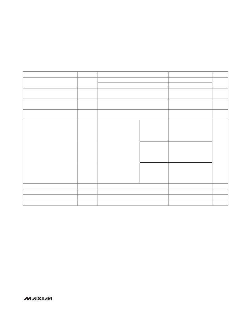
+3.3V SUPPLY AC ELECTRICAL CHARACTERISTICS (continued)
(Typical Application Circuit, RF and LO ports are driven from 50 Ω sources, Typical values are at V CC = +3.3V, P RF = -5dBm,
P LO = 0dBm, f RF = 2500MHz, f LO = 2200MHz, f IF = 300MHz, T C = +25°C, unless otherwise noted.) (Note 6)
PARAMETER
3RF-3LO Spur Rejection
SYMBOL
3x3
P RF = -10dBm
P RF = -5dBm
CONDITIONS
MIN
TYP
67.9
57.9
MAX
UNITS
dBc
RF Input Return Loss
LO Input Return Loss
LO on and IF terminated into a matched
impedance
RF and IF terminated into a matched
impedance
16
16.7
dB
dB
IF Output Impedance
Z IF
Nominal differential impedance at the IC’s
IF outputs
RF terminated into 50 Ω ,
f IF = 450MHz,
LO driven by 50 Ω source,
L1 = L2 = 120nH
IF transformed to 50 Ω
200
23
Ω
using external
components shown in the
IF Output Return Loss
Typical Application
Circuit . See the IF Port
Return Loss vs. IF
f IF = 350MHz,
L1 = L2 = 270nH
23
dB
Frequency graph in the
Typical Operating
Characteristics for
performance vs. inductor
values.
f IF = 300MHz,
L1 = L2 = 470nH
23
Minimum RF-to-IF Isolation
Maximum LO Leakage at RF Port
Maximum 2LO Leakage at RF Port
Maximum LO Leakage at IF Port
f RF = 2300MHz to 2700MHz, P LO = +3dBm
f LO = 1900MHz to 2500MHz, P LO = +3dBm
f LO = 1900MHz to 2500MHz, P LO = +3dBm
f LO = 1900MHz to 2500MHz, P LO = +3dBm
33
-26.6
-28.8
-21.9
dB
dBm
dBm
dBm
Note 5:
Note 6:
Note 7:
Note 8:
Note 9:
100% production tested for functional performance.
All limits reflect losses of external components, including a 0.8dB loss at f IF = 300MHz due to the 4:1 impedance trans-
former. Output measurements were taken at IF outputs of the Typical Application Circuit.
Not production tested. Operation outside this range is possible, but with degraded performance of some parameters. See
the Typical Operating Characteristics.
Maximum reliable continuous input power applied to the RF or IF port of this device is +12dBm from a 50 Ω source.
Measured with external LO source noise filtered so that the noise floor is -174dBm/Hz. This specification reflects the
effects of all SNR degradations in the mixer including the LO noise, as defined in Application Note 2021: Specifications
and Measurement of Local Oscillator Noise in Integrated Circuit Base Station Mixers.
_______________________________________________________________________________________
5
发布紧急采购,3分钟左右您将得到回复。
相关PDF资料
MAX19997AETX+T
IC DOWNCONVERTER 2CH 36TQFN
MAX19998ETP+
IC MIXER DOWNCONVERSION 20TQFN
MAX19999ETX+T
IC DOWNCONVERTER 2CH 36TQFN
MAX2009ETI+T
IC RF PREDISTORT ADJ 28-TQFN
MAX2010ETI+T
IC RF PREDISTORT ADJ 28-TQFN
MAX2014ETA+T
IC DETECT/CNTRL LOG 8-TDFN
MAX2015EUA+T
IC DETECT/CNTRL LOG 8-UMAX
MAX2015EVKIT
EVAL KIT FOR MAX2015
相关代理商/技术参数
MAX19997
功能描述:上下转换器 RoHS:否 制造商:Texas Instruments 产品:Down Converters 射频:52 MHz to 78 MHz 中频:300 MHz LO频率: 功率增益: P1dB: 工作电源电压:1.8 V, 3.3 V 工作电源电流:120 mA 最大功率耗散:1 W 最大工作温度:+ 85 C 安装风格:SMD/SMT 封装 / 箱体:PQFP-128
MAX19997AETX+
功能描述:上下转换器 High-Gain 1.8GHz to 2.9GHz Downconv RoHS:否 制造商:Texas Instruments 产品:Down Converters 射频:52 MHz to 78 MHz 中频:300 MHz LO频率: 功率增益: P1dB: 工作电源电压:1.8 V, 3.3 V 工作电源电流:120 mA 最大功率耗散:1 W 最大工作温度:+ 85 C 安装风格:SMD/SMT 封装 / 箱体:PQFP-128
MAX19997AETX+T
功能描述:上下转换器 High-Gain 1.8GHz to 2.9GHz Downconv RoHS:否 制造商:Texas Instruments 产品:Down Converters 射频:52 MHz to 78 MHz 中频:300 MHz LO频率: 功率增益: P1dB: 工作电源电压:1.8 V, 3.3 V 工作电源电流:120 mA 最大功率耗散:1 W 最大工作温度:+ 85 C 安装风格:SMD/SMT 封装 / 箱体:PQFP-128
MAX19998AETP+
功能描述:上下转换器 High-Gain 2.3GHz to 4.5GHz Downconv RoHS:否 制造商:Texas Instruments 产品:Down Converters 射频:52 MHz to 78 MHz 中频:300 MHz LO频率: 功率增益: P1dB: 工作电源电压:1.8 V, 3.3 V 工作电源电流:120 mA 最大功率耗散:1 W 最大工作温度:+ 85 C 安装风格:SMD/SMT 封装 / 箱体:PQFP-128
MAX19998AETP+T
功能描述:上下转换器 High-Gain 2.3GHz to 4.5GHz Downconv RoHS:否 制造商:Texas Instruments 产品:Down Converters 射频:52 MHz to 78 MHz 中频:300 MHz LO频率: 功率增益: P1dB: 工作电源电压:1.8 V, 3.3 V 工作电源电流:120 mA 最大功率耗散:1 W 最大工作温度:+ 85 C 安装风格:SMD/SMT 封装 / 箱体:PQFP-128
MAX19998AEVKIT#
制造商:Maxim Integrated Products 功能描述:SIGE HIGH-LINEARITY 2300MHZ TO 4000MHZ DOWNCONVERSION MIXER - Boxed Product (Development Kits)
MAX19998ETP+
功能描述:上下转换器 High-Gain 2.3GHz to 4.5GHz Downconv RoHS:否 制造商:Texas Instruments 产品:Down Converters 射频:52 MHz to 78 MHz 中频:300 MHz LO频率: 功率增益: P1dB: 工作电源电压:1.8 V, 3.3 V 工作电源电流:120 mA 最大功率耗散:1 W 最大工作温度:+ 85 C 安装风格:SMD/SMT 封装 / 箱体:PQFP-128
MAX19998ETP+T
功能描述:上下转换器 High-Gain 2.3GHz to 4.5GHz Downconv RoHS:否 制造商:Texas Instruments 产品:Down Converters 射频:52 MHz to 78 MHz 中频:300 MHz LO频率: 功率增益: P1dB: 工作电源电压:1.8 V, 3.3 V 工作电源电流:120 mA 最大功率耗散:1 W 最大工作温度:+ 85 C 安装风格:SMD/SMT 封装 / 箱体:PQFP-128
